De
De  Es
Es  Fr
Fr  En
En 

-
-
-
-
-
-
-
-
-
-
-
-
-
-
-
-
-
-
-
-
Ortho Texture Overlay
-
-
Ortho Texture Overlay
 Ribbon: 3DScan – Texturing and Calculations >
  Ortho Texture Overlay
Menu: 3DScan – Texturing >  Ortho Texture Overlay
Toolbar: Texturing and Calculation > Orthogonal Texture
Toolbar: Meshes 3DScan > Ortho Texture Overlay
 Command line: PC_ORTHO_TEXTURE
The command creates a textured surface, if a drawing contains a point cloud with the Scan color attribute (its display should be enabled) and the surface created according to this point cloud. The command can be used to create a photorealistic model of the earth's surface.
After starting the command, specify the Mesh object in the drawing.
The command options are set on the Properties bar.
Options:
|
Texture Size |
Generated texture size in pixels. |
|
Format |
The BMP, JPG, PNG and TIFF formats are available. |
|
From Ground |
If Yes, the color of the cloud points will be projected onto the surface, as if looking from the ground. If No is selected, the color will be projected as if viewed from above. |
Command prompts:
|
Apply changes? <Yes> or [Yes/No/Save/saveDefault] <Yes>: |
Yes – the command will be performed taking into account changes in the settings made by the user in the current session of the command work. No – the command will be performed with the settings displayed immediately after running the command. Save – saving settings to a document. saveDefault – saving settings to the registry. |
|
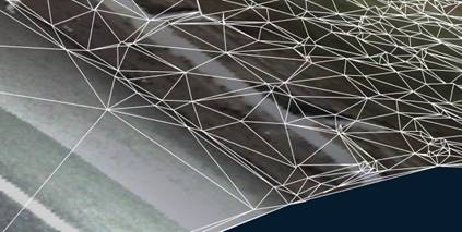
Mesh before texturing |
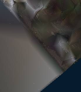
Mesh after texturing |
|
|
|
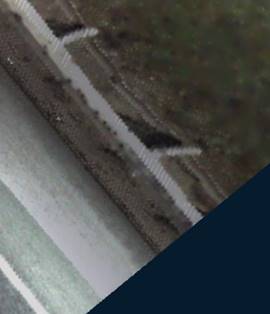
After removing the point cloud from the drawing, the surface retains the texture: